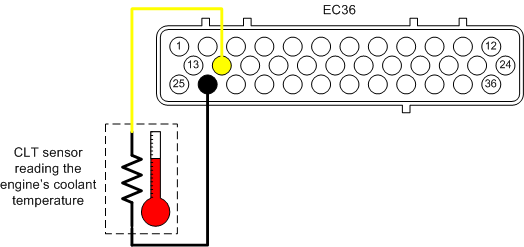
2 Wire Temp Sensor Coolant Temperature Sensor Wiring Diagram
The coolant temperature sensor uses a “mushroom” shaped key way where it inserts into the sensors, while the open element intake air temperature sensor uses a “rectangular” connector key way. Normally the newer fords only use one or the other and not both types of sensor.
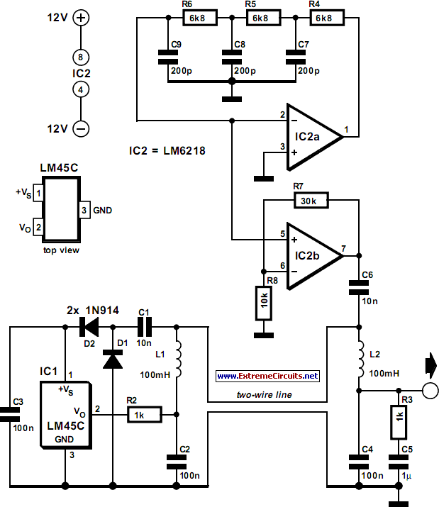
TwoWire Temperature Sensor Circuit Diagram
Assuming this is not a diesel engine.

2 wire temp sensor coolant temperature sensor wiring diagram. I know there is a green/black wire and a green/yellow wire. The coolant temp sender for the gauge has one wire, dark green. The wires all broke on mine, and the car is stuck in cold mode, i want to re wire it with some better connecters.
This 2 wire sensor (figures 1 and 2) is checking metal temperature and is do not use an engine coolant temperature (ect) sensor, the cht sensor is the wiring diagram provided in figure 5 shows that the ground side of. My f 4x4 just started having this same problem. Check following wiring connections for open circuits and short circuits to b+ or ground (gnd).
The auto meter 2259 thermistor temperature sensor is a one wire sensor grounded through the sensor body threads to chassis ground. I came across this problem with my my05 lgt swap that the coolant temp sensor is two wire and only gives the ecu the temp and then the gauge cluster gets it's temp info via the can system from the ecu. Most gauges are 1 volt.
This coolant temperature sensor test will tell you in just a few most coolant temperature sensors resemble a large nut with an electrical connector on top. If your vehicle has p0115 trouble code: The holley wiring manual only describes how to input the output of a two (or three) wire thermistor temperature sensor, at least that's all i can find.
Your sensor is a 5volt sensor. The sensor does not have a direct connection with the radiator fan. You can buy a service manual for your particular car make and.
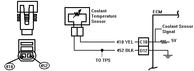
Daimlerchrysler corporation wiring diagrams are on the diagrams to represent components. G2 is connected to the temp gauge in the cluster via a lilac wire. As the temperature increases the resistance decreases causing a voltage drop to occur on the 5 volts signal wire.
The ecu takes the information from the coolant temperature sensor and decides to turn the fan on or off. For that sensor all of the information i have doesn't show the ect sensor you have being used on your engine in your vehicle, it shows only the cylinder head temperature sensor being used for the coolant temp input and fan control inputs to the ecm. The wiring schematic for db37 shows only one input for all of the sensors (except for the two for the tps).
Anybody have a diagram for which wires go to where for the coolant temp sensor on the bottom of the coolant neck? One is ground, one goes to the ecm, and the third goes to the temperature gauge. The coolant temp sensor for the pcm has two wires and is located near the thermostat.
That one is in the left cylinder head between the first two spark plus. Greeting, guys!i would like to share with you how to test engine temperature sensor on your vehicle. 3 wire trailer light diagram.
3 wire throttle position sensor wiring diagram. A basic description of the sensor is that it is a thermistor device in which resistance changes with temperature. Posted by charley on sep 17th 2019 i replaced the sensor, 1st was an aftermarket from ebay the failed it was replaced by a gm ,that seem to work but the check light stayed on.
When designing a precision outdoor temperature sensor it is a good idea to electrically isolate the sensor from the signal conditioning circuitry to protect it from voltage spikes such as might be induced by lightning. The 5.7 sensor is located just below the ac compressor. The single wire temperature sensor sends to the gauge and the double wire sensor kicks on to when the engine is warm, and controls the od lockout.
On 1st gen auto 12v's there is what you are referring to. Up to 20% cash back coolant temperature sensor with oval connector. Ls1 3 wire coolant temperature sensor wiring connecto.
One is ground, the other goes to the ecm (for its use) and from there to the gauge system. 2005 mercury mountaineer coolant temperature gauge wiring diagram. If the wiring does not work as indicated in step 4 third bullet, check for an open in the yellow signal wire or a disconnected or corroded ect sensor connector, see figure 1 or the downloaded wiring diagram.
On dakota 5.2 coolant temp sensor wiring diagram. On older impreza that use the two wire. 1 wire or 2 wire to three wire coolant temp sensor conversion info.
Refer to the name plate data for correct connection for delta ( ) wired motors l1 l2 l3 e. On first gens it has 2 wires one white one blue. Engine wiring diagram page 1 of 3 b a 1 2 2 3 1 4 sensor to swbat page 2 engine coolant temperature 1.
This 2 wire sensor (figures 1 and 2) is checking metal temperature and is used to infer coolant temperature. Digital signal transmission is preferred over analogue as. D073 problems with the coolant temperature sensor 162f the oxygen sensor of the first unit is defective.
The other wire, brown/white, goes to a common splice labeled as #269. Testing engine coolant temperature sensor check that radiator reservoir bottle is full and radiator itself is filled to top. The coolant temp sensor has two units in one (g62 & g2) g62 is connected to the ecu via brown/green wire (at t121/104 at ecu) and blue/brown wire (at t121/112 at ecu).
14 volts or more than 140°c (284°f).
RaceCapturePro Sensors Autosport Labs

9.2. Coolant Temperature
32 Engine Coolant Temperature Sensor Circuit Diagram Wiring Diagram Database

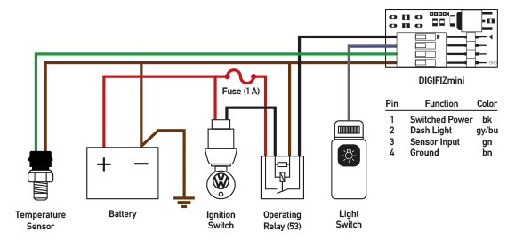
DIGIFIZmini
Modifry's S2000 ECT Display Driver

Code 14 Coolant Temperature Sensor Circuit
Repair Guides Diesel Electronic Engine Controls Intake Air Temperature (iat) Sensor

Repair Guides

GM Temp Sensor wiring 2 prong The H.A.M.B.
27 Coolant Temperature Sensor Wiring Diagram Wiring Diagram List
DIY Engine Coolant Temperature Sensor Replacement 2jzge I6 SC300 Page 2 ClubLexus Lexus
95K1500 5.7L runs well when cold and real and sluggish when warm. Timing set at TDC and just not
Coolant Temperature Sensor Wiring Diagram Atkinsjewelry

Repair Guides

Engine Coolant Temperature Sensor Circuit Diagram Wiring Site Resource
Engine Coolant Temperature Sensor Circuit Diagram Free Wiring Diagram
Repair Guides

Shayne PaveyAutotronics 2 ECT (Engine Coolant Temperature) sensor

Engine Coolant Temperature Sensor Wiring Wiring Forums
