Accelerator Pedal Position Sensor Wiring Diagram
So, a 6 pin accelerator pedal position sensor wiring diagram is, two wires are for the earth, two for the input voltage, and two for signals back to the computer (ecu). Also i show you how you can figure out what each wire on your sensor i.
35 Accelerator Pedal Position Sensor Wiring Diagram Wire Diagram Source Information
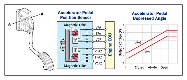
Potentiometer 1 generates a signal of 0.3 to 4.8 volts (red trace in figure 3 ) and potentiometer 2 generates a signal of 4.8 to 0.3 volts (blue trace in figure 3 ).
Accelerator pedal position sensor wiring diagram. You’ll be in a position to understand specifically once the tasks ought to be completed, which makes it easier for you personally to effectively manage your time and. Its electrical circuitry is the same as the accelerator pedal position sensor. Accelerator pedal position sensor wiring diagram wiring diagram is a simplified satisfactory pictorial representation of an electrical circuit it shows the components of the circuit as simplified shapes and the skill and signal links amongst the devices.
Ł b+ when the pedal is depressed the ivs receives a 12 v ignition voltage at pin f from the ignition fuse in the power distribution box. However, it’s not the only code related to the throttle body and its circuitry. Accelerator pedal position sensor video demonstrating
The aps is grounded from connector terminal b to the ecm signal ground Apr 10, 2018 at 12:18 pm. February 17, 2022 posted by enduro mountain bike magazine.
Monster bar disposable wholesale / pedal assist sensor wiring diagram. If you are searching for cat accelerator pedal position sensor wiring diagram, you are at the right site. But, it doesn’t mean link between the cables.
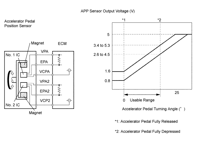
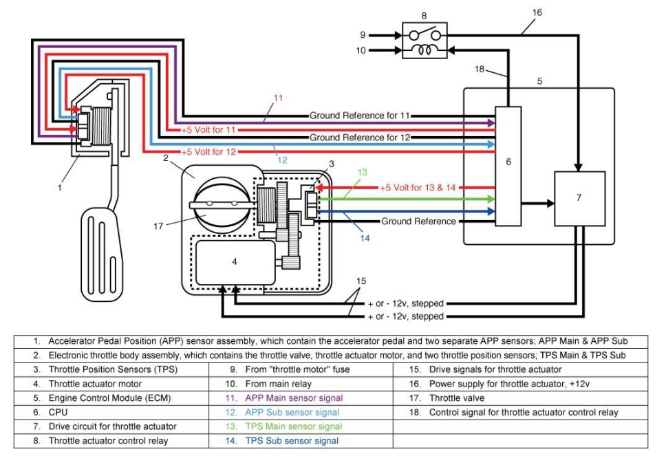
Injunction of 2 wires is usually indicated by black dot in the junction of 2 lines. That app sensor 1's signal increases as the accelerator pedal is depressed, from below 1.1 volt at 0% pedal travel (pedal at rest) to above 2.1 volts at 100% pedal travel (pedal fully depressed). Aps/ivs accelerator position signal in range dtc aps/ivs install the 5 wire breakout.
Based on this information the load requested by the driver can be implemented immediately. Pedal assist sensor wiring diagram. The aps returns a variable voltage signal (depending on pedal position) from the aps connector terminal a to the ecm at terminal 8.
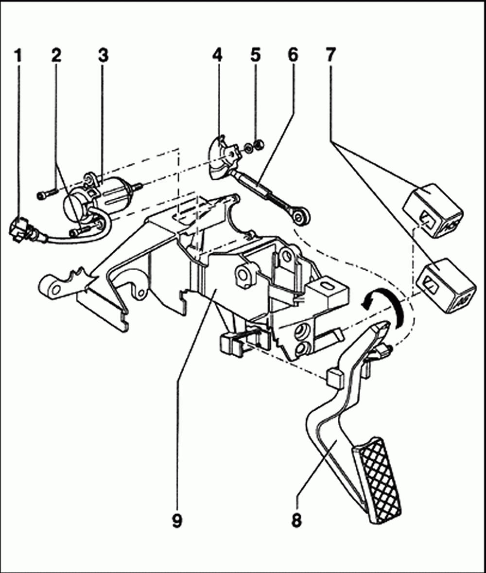
The accelerator pedal position sensor is installed on the upper end of the accelerator pedal assembly. Pedal assist sensor wiring diagram. These sensors are a kind of potentio meter which transform the accelerator pedal position into output voltage, and emit.
The sensor detects the accelerator position and sends a signal to the ecm. Flank steak with bloody mary tomato salad; In modern throttle control systems, the throttle position sensor is used to detect the position of the throttle valve integrated into the actuator motor.
Ford car sensors and wiring diagram sensors and wiring diagram. With an accelerator pedal position of 45 degrees, potentiometer 1 may be outputting a signal of 2 volts and potentiometer 2 a signal of 3 volts, for example. I would download the schematics/block diagrams for the accelerator sensor circuits and start testing.
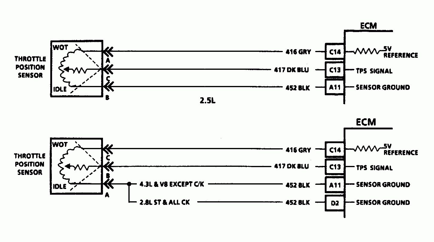
Accelerator pedal position sensor wiring diagram wiring diagram is a simplified satisfactory pictorial representation of an electrical circuit it shows the components of the circuit as simplified shapes and the skill and signal links amongst the devices. Occasionally, the wires will cross. As stated previous, the lines at a throttle position sensor wiring diagram represents wires.
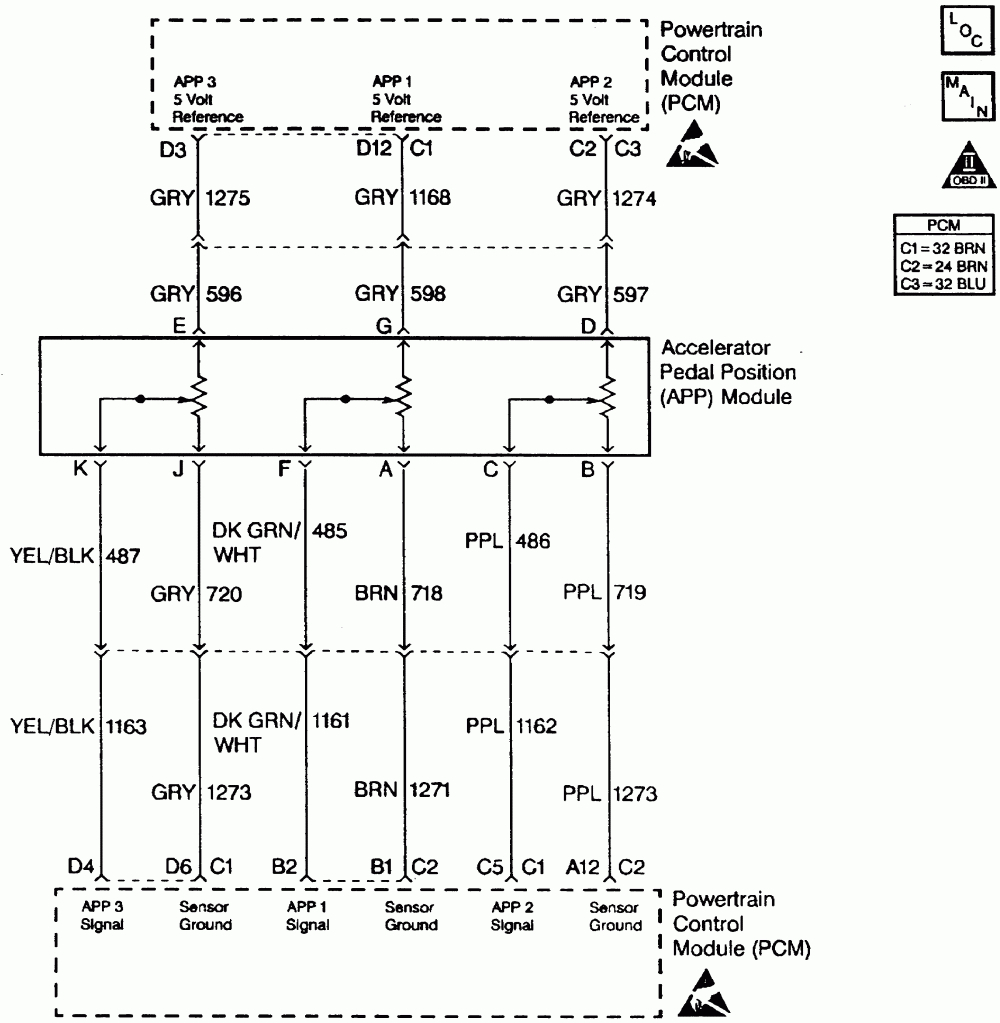
That the accelerator pedal assembly is made up of 3 individual position sensors. Cat accelerator pedal position sensor wiring diagram. The p2138 trouble code is triggered when there are problems with the throttle/pedal position sensor/switch.
Each one has separate signal, ground, and 5.0 volt reference circuits. Accelerator position sensor (aps) the ecm sends a regulated 5v signal through the ecm black chassis connector terminal 3 to aps connector terminal c. The p2135, p2136, p2137, p2139, and p2140 dtcs also indicate issues in.
• 0 v when the pedal is at the idle position. Here is a quick video on how to test a throttle position sensor tps with a multimeter. It's possible you did something to a wire or have a bad ground (did you disconnect your battery or anything in the.
Omgwtfbbq!, apr 10, 2018 #6. A throttle position sensor or tps is an accelerator pedal sensor without a pedal arm. Accelerator pedal position sensor wiring diagram wiring diagram is a simplified satisfactory pictorial representation of an electrical circuit it shows the components of the circuit as simplified shapes and the skill and signal links amongst the devices.
There will be principal lines that are represented by l1, l2, l3, and so on. We provide some wiring diagram for cat 5. Is south korea safe for female travellers;
We collect plenty of pictures about 2003 dodge ram 2500 57 hemi throttle body wiring diagram. Pedal assist sensor wiring diagram pedal assist sensor wiring diagram. When the pedal is not in the idle position (throttle applied), the ivs supplies a 12 v signal to the ecm.
Accelerator pedal position sensor has two sensors. It has 2 sensor terminals (vpa and vpa2) to detect the accelerator pedal position and a malfunction. It shows the components of the circuit as simplified shapes, and the skill and signal links amongst the devices.
Troubleshooting the pedal position sensor is gonna be difficult.
Accelerator Pedal Position Sensor Wiring Diagram Drivenheisenberg
P0122 Throttle position (TP) sensor A/accelerator pedal position (APP) sensor / switch A low

Accelerator Pedal Position Sensor Wiring Diagram Wiring Diagram
Accelerator Pedal Position Sensor Wiring Diagram Wiring Diagram
Accelerator Pedal Position Sensor Wiring Diagram Diagram For You
Repair Guides Diesel Electronic Engine Controls Accelerator Pedal Position (app) Sensor

Accelerator Pedal Position Sensor Wiring Diagram Diagram Resource Gallery
VZ LS1 Accelerator Pedal Position Sensor Page 3 Just Commodores
Accelerator Pedal Position Sensors (APPS)
Repair Guides Automatic Transaxle (2003) Dtc P1705 Accelerator Pedal Position Sensor

28 Accelerator Pedal Position Sensor Wiring Diagram Wiring Diagram List
Repair Guides

Accelerator Pedal Position Sensor Wiring Diagram Wiring Diagram
Throttle position sensor problem?
Repair Guides Automatic Transmission (2004) Dtc P1705 Accelerator Pedal Position Sensor
Gm Accelerator Pedal Position Sensor Wiring Diagram For Your Needs

Accelerator pedal position (APP) sensor wiring diagram Anyone help? CorvetteForum
35 Accelerator Pedal Position Sensor Wiring Diagram Wire Diagram Source Information
Nissan accelerator pedal position (APP) sensor
