Mobile Charger Circuit Board Design
Use existing products to use more benefits. Knowing to design a circuit is the basic skill of an electrical and electronics engineer.
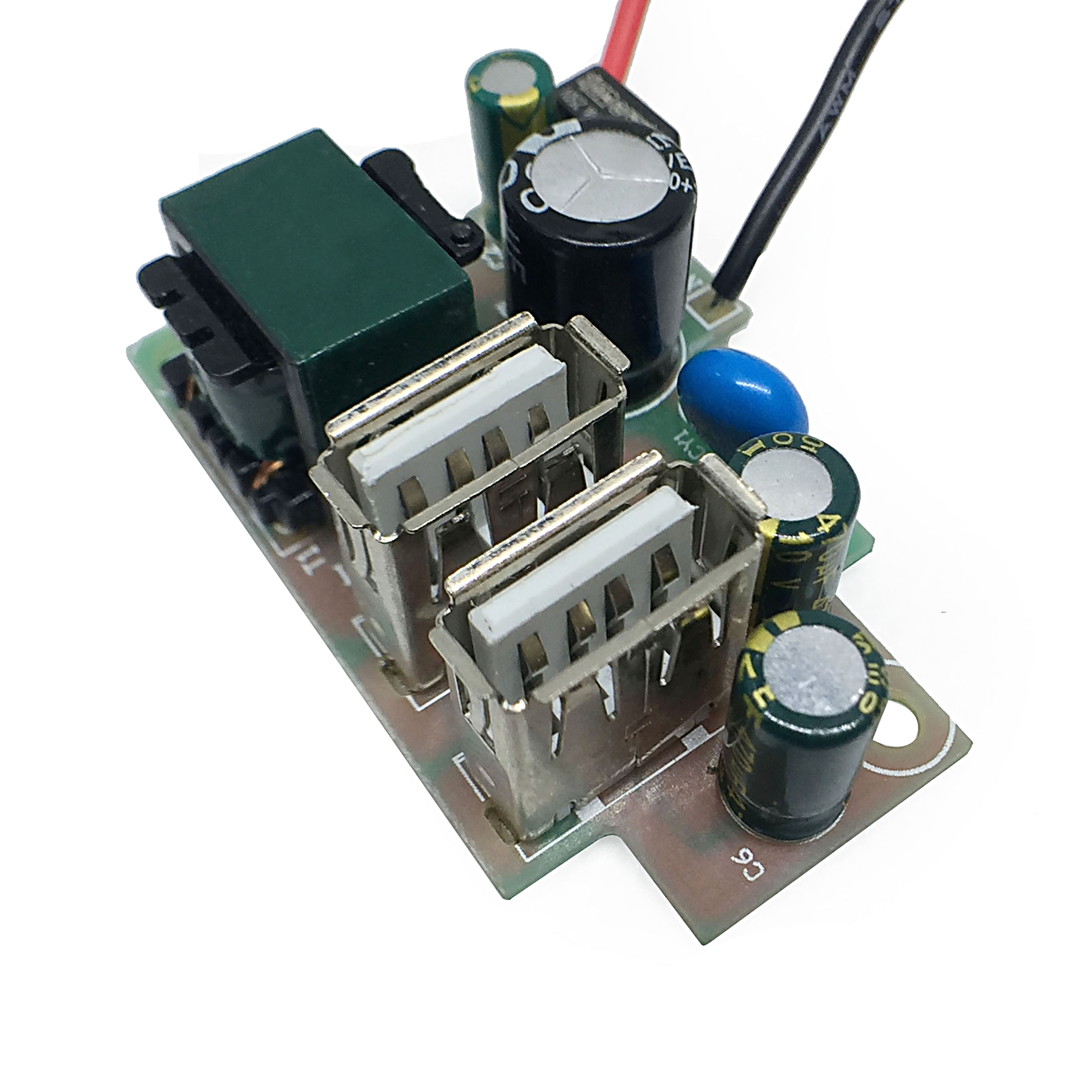
Design Usb Wall Outlet Mobile Charger Pcb Pcba Circuit Board Buy Usb Wall Outlet Product on
I have done this in two ways.

Mobile charger circuit board design. We also include mobile phone circuit board parts, mobile pcb diagram, mobile pcb board diagram and smart phone pcb repairing updated information 2019 on mobile pcb board components pdf here in this blog post. We use the concept of the circuit: These documents help engineers incorporate particular solutions into specific applications.
Accelerate your system design and time to market with tested schematics, boms and design files from ti’s reference design library. Image used courtesy of power integrations. The radio frequency link establishes a connection to the switching systems of a mobile phone.
I made two footprints for vector pins. This is the first automatic battery charger circuit. As leon suggested i would use pcb design program.
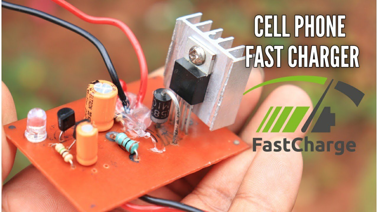
Place a couple of these patterns down and you have a large grid. You don't give your batteries a day off — so your charger better be able to keep up. In this project we will build a similar ac to dc power supply circuit with 10w.
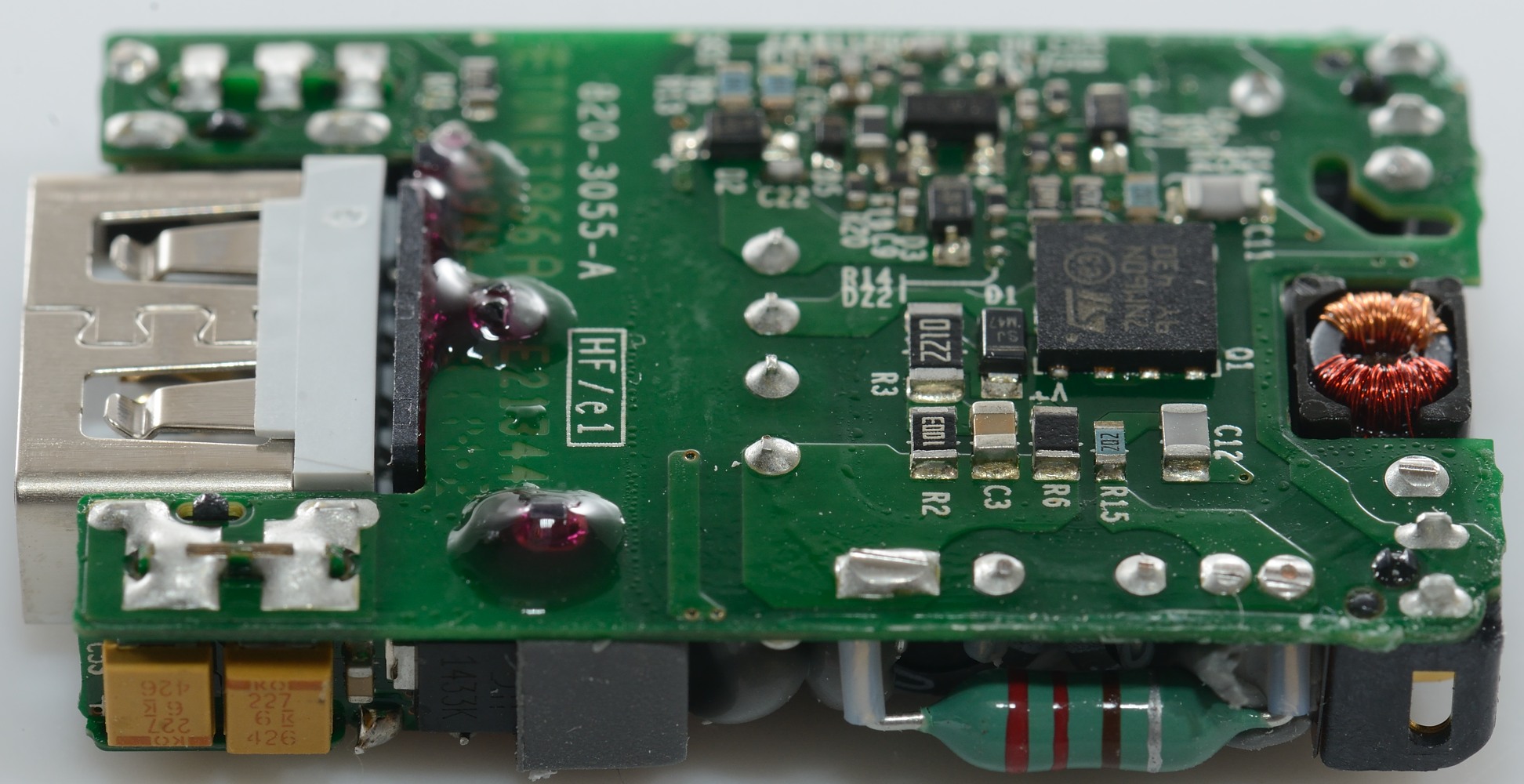
Using the standard porsche mobile charger plus you can charge on a 120v 10 amp traditional household socket up to 240v 50 amp circuit with a range of sockets to choose from at no cost when ordering your vehicle. We can use this circuit for all battery. One for the battery protection and charge circuit, and the usb boost converter on another circuit, mounted perpendicular to the first.
The pcb and the charger are supposed to last for ten years. Place the mobile phone over the cardboard and test the charger circuit. The second design explains a cheap yet effective, less than $1 cheap yet effective solar charger circuit, which can be built even by a layman for harnessing efficient solar battery charging.
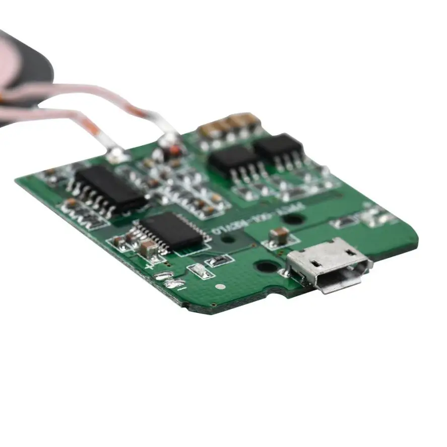
Simple automatic battery charger circuit. Mobile technology has become one of the fastest growing technologies in the world. After the product is tested, desolder all the coil connections from the circuit board.
If you use the external circuit a, replace the rx with a jumper wire in the pcb. Hello shubham, the above circuit won't be required for mobile to mobile charging application….a boost converter circuit could be tried for the purpose, and to implement it successfully the charger mobile battery must be rated higher in terms of its ah rating. A mobile phone, cellular phone, cell phone, cellphone, handphone, or hand phone, sometimes shortened to simply mobile, cell or just phone, is a portable telephone that can make and receive calls over a radio frequency link while the user is moving within a telephone service area.
He solar panel can be used as a component of a larger photovoltaic system to generate and supplyelectricity in. Depending on the input voltage.” This audio frequency amplifier is ideal for small battery powered devices.
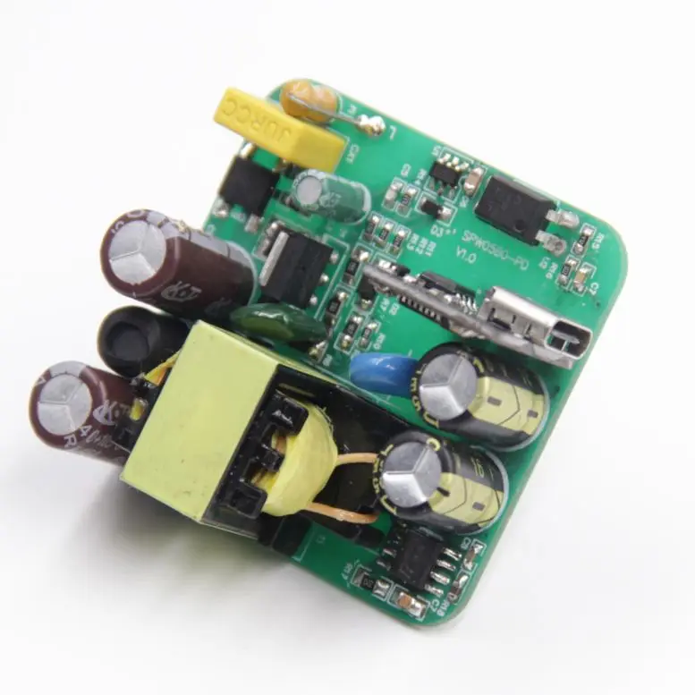
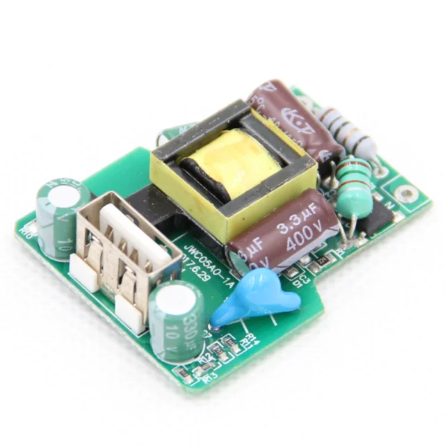
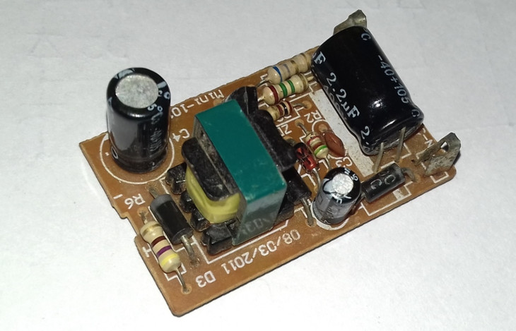
Most household electronic products like mobile chargers, bluetooth speakers, power banks, smart watches etc requires a power supply circuit that could convert the ac mains supply to 5v dc to operate them. The manufacturer made the pcb (printed circuit board) as one solid piece without any moving parts. Only continue if the charger performs well, if not return the product or get an exchange.
A mobile cell phone is a hand held mobile device that can perform several communication functions. Just have to understand battery charging requirements only. This circuit constructed to produce high frequency magnetic flux.
The above circuit of the wireless electronic notice board using gsm consists of 8051 microcontroller, gsm module (modem) and 16 x 2 lcd. Not using ics and complicated devices. Nowadays mobile phones have become an integral part of everyone’s life and hence require frequent charging of battery owing to longer duration usage.
Circuit design 10+ simple proteus circuit design projects and examples for beginners dineshkumar e. From simple calculators to mobile phones and laptops, everything is made possible because of the electronics circuit. You will need just a solar panel panel, a selector switch and some diodes for getting a reasonably effective solar charger set up.
The daughter board has been split into a 2 piece design now and connects on the sides of the mother board versus the middle as every. The center tapped coil is made through 20 swg enameled copper wire 6 cm dia and 5. An alternative charger circuit is also provided to charge the mobile by house hold general purpose 230v in the absence of the sun light.
Take note that the circuit c is to be connected between pins 1 and 5 of the ic. This was a smart design choice as it allows anker to make revisions to each board independently of the other, and provides them with more flexibility in. Means, we need 8 data lines to display the data.
Apart from the ic, a transistor (bc 548) is used to control the charging current supplied to battery. Power supply unit (psu) is a vital part in any electronic product design. Mobile phones generally charge with 5v regulated dc supply, so basically we are going to build a circuit diagram for 5v regulated dc supply from 220 ac.
A mobile battery charger circuit is a device that can automatically recharge a mobile phone’s battery when the power in it gets low. The maxrefdes73# reference design is a wearable, mobile galvanic skin response system. Sometimes i just use vias to create a matrix.
Today people use mobile phones to stay in touch with friends and family, to share stories and photographs in social media, and to carry out financial transactions. The reason for that is to prolong the life of the board because any moving part inside the board will cause problems with time. This dc supply can be used to charge mobiles as well as the power source for digital circuits, breadboard circuits, ics, microcontrollers etc.
The power output is around 550 mw at 16 ohm speaker impedance. Create a land pattern that is a strip of holes or a matrix of holes (no silkscreen). Good phone doctors must also learn how to identify spare parts, android phone parts, and how each parts of android phone work on a.
It is designed for 12v batteries.
Design Usb Wall Outlet Mobile Charger Pcb Pcba Circuit Board Buy Usb Wall Outlet Product on
Test of Apple USB power adapter
Pcba Manufacturer Oem Pcb Board Pcb Design Mobile Charger Circuit Board Buy Pcba Mobile

OEM ODM Dual USB 5V 2A 2.1a 2.22 Amp Charger Pcba 10w PCB Circuit Board Assembly 5v2.1a Mobile

AC Mobile Charger Circuit Board at Rs 13 /piece(s) Cell Phone Charger Circuit Board, Cellphone

China One Stop Solution USB PCB Assembly Electronic Mobile Phone Charger Circuit Board

Mobile Phone Charger Circuit Board Cell Phone Charger Circuit Board Latest Price

DIY Qi wireless charger Universal Printed Circuit Board from the Wireless Charging Coil Wireless
12 V Battery Charger Circuit PCB, Water Circuit Board, सर्किट बोर्ड in Pune , Innovators Guru

PCBA Circuit Board For Quick Charge 3.0 Mobile Phone Charger Wall Charger Dual USB Charger AC

2.1 Amp PCB Mobile Charger Circuit Board for Electronics, Rs 28 /piece ID 16973124562

Mobile Charger PCB Board at Rs 13/piece Mobile Phone Charger Circuit Board ID 17028339388

Fast Quick Charger QC3.0 QC2.0 3V 5V 12V Mobile Charger Circuit Board Module in Pakistan Maaz

USB Mobile Power Charging Circuit Board Mini USB Port 1A Lipo Battery Charger Modulein Chargers

Cell phone charger DIY fast mobile charger circuit and free PCB layout YouTube
Mobile charger circuit diagram, 100220V AC Circuits DIY
China PCBA Circuit Board Usb Assembly Mobile Phone Charger QC3.0 Wall Charger Dual USB Charger
Mobile Charging PCB Bord, Cell Phone Charger PCB, Cell Phone Charger Printed Circuit Board
Power Bank Mobile Charger Board Circuit Dual USB Output StepUp Module 5V 2A eBay
